Installation
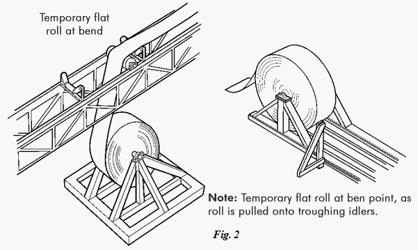
Once the roll of belting has been transported to the point of installation, it should be mounted on a suitable shaft for unrolling and threading onto the conveyor. Conveyor belting is normally rolled at the factory with the carrying side out. Consequently, in mounting the roll, the belt must lead off the top of the roll if it is being pulled onto the troughing or carrying idlers, but off the bottom of the roll if it is being pulled onto the return idlers. When pulling the belt onto the conveyor, the roll will turn opposite the direction indicated by the arrows on the crate. Fig. 2 illustrates a suitable method of mounting, as well as leading off the top of the roll for pulling onto the troughing idlers.
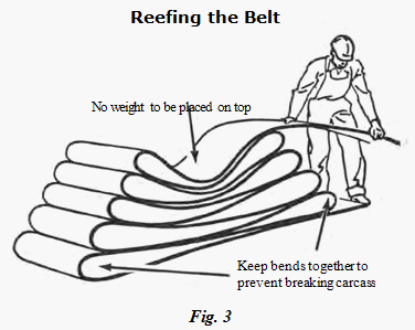
In some cases, such as in mines where headroom does not permit maneuvering a roll, the belt may have to be pulled off the roll and reefed (Fig. 3). Extreme care should be exercised to see that the loops have large bends to avoid kinking or placing undue strain on the belt, and no weight should ever be placed on the belt when it is in this position. Ideally, supports should be placed at each end where the bends occur.
A third method of handling the roll, where headroom for mounting on a horizontal shaft is lacking, is mounting on a turntable with a vertical spindle. The belt must make a 90-degree twist as it comes off the turntable. This method is sometimes used underground, with the turntable mounted on wheels or skids for transporting the roll of belt as it lies on its side, as well as for unrolling it at the final location.
If the belt is for replacement, the new roll can be set up as previously indicated. The old belt is clamped off and cut, and the new belt is spliced to the leading end of the old belt by using approximately one-half the usual number of plate-type fasteners. The trailing end of the old belt is hooked to a truck, tractor, mine locomotive, or other means of providing traction. The conveyor drive motor is used to pull on the new belt while the towing device drags the old belt away and at the same time provides sufficient slack side tension for the conveyor drive pulley. In all cases, care should be exercised to ensure the carrying side of the conveyor is placed upward if pulling onto the top run, or downward if pulling onto the return run.
For a new conveyor installation having little or no slope, a rope or cable should be attached to a clamp at the belt end. In clamping to the end of the belt for pulling it on the conveyor, it is not sufficient to cut a hole through the belt or ears into its corners for tying on a rope. A clamp should be made to distribute the pull applied to the end across its full width. Since the clamp must pass through places of low clearance, it usually is made of two pieces of 1/4-inch to 1/2-inch plate approximately equal to the belt width and 4 inches long. One piece is placed against each surface of the belt at the end, and bolts are placed through both plates at about 6-inch intervals and 2 inches back from the belt end. The rope is then attached to this clamp with a shackle or by welding an eye to one of the plates. The belt roll has been handled as previously described. The rope or cable is then threaded over the conveyor and attached to a towing device to pull the belt onto the conveyor.
For installations with a relatively high degree of slope (12 degrees or more), the method of handling is slightly different. The roll of belt is set up as previously described. It is often found most convenient to place it at or near the head pulley, since this generally is the most accessible. Assuming the conveyor is sufficiently long to require more than one splice, the conveyor side and the return sides are threaded on separately. Care must be taken to see that conveyor side or heavier cover is up on the carrying side and down on the return run.
As the belt is fed on, the tension at the roll tends to build up due to the weight of the belt on the slope. For this reason, some method of braking is required. Customary practice is to use a belt clamp, mounted on the conveyor structure, through which the belt is threaded. Where the slope is very long, additional clamps should be spaced approximately 1000 feet apart. Where more than one clamp is used, workers are stationed at each clamp to loosen and tighten the clamps as the belt is fed onto the conveyor. Care must be exercised that the belt does not run away. As a roll runs out, another is spliced on and then fed onto the conveyor.
If the conveyor side and the return side have been fed on separately, the final splice is best made at the bottom of the slope where the ends of the belt meet, since a much lower splicing tension will serve at this point. Making the final splice at the top of the slope is entirely possible but requires proper splicing tension.
When pulling the belt onto the system, station personnel at key points along the conveyor to help avoid the belt from hanging up on the structure resulting in belt damage. Pull the belt ends until they overlap the required splicing length.
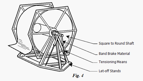
To prevent the belt roll from over-running at the let-off, a braking device is often needed (Fig. 4).
TENSIONING
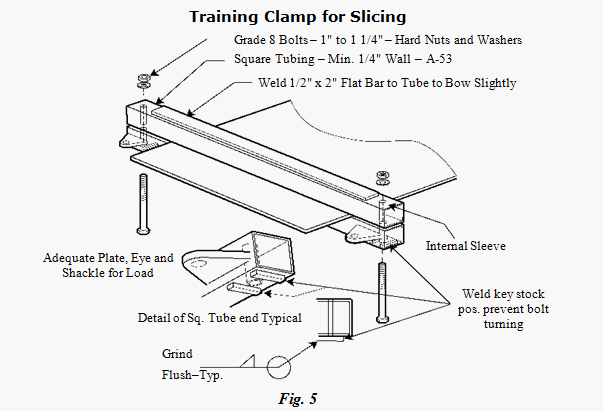
Once the belt has been pulled onto the conveyor system, it must be tensioned prior to splicing to facilitate correct positioning of the take-up and to eliminate sag. The tensioning operation takes place at the location where the last splice will be made. After final tensioning, clamps are placed on each end of the belt. These are made of steel and have a clamping surface as indicated in Figure 5.
Tension is applied by means of a power device, which is used to pretension the belt before “clamping off.” When tension measuring load cells or scales are used, they are rigged to measure the pull on the take-up pulley. The belt is pulled until the load cells or scales register a tension equal to or slightly greater than the recommended take-up force. Make allowance for an amount of belt necessary to correctly position the counterweight from this point. Certain basic statements and recommendations can be made about tensioning for splicing:
- Belts which are tensioned by pulling in only one direction require more splicing tension than those pulled in both directions.
- Slope belts spliced at the top of the slope require more splicing tension than those spliced at the bottom.
- Slope belts with an anti-rollback device that cannot be released must be tensioned by pulling only in the direction of belt travel.
- Check the belt frequently during tensioning to ensure that the belt is free and not binding at any place.
- During the final tensioning pull, be sure the ends of the belt are lined up properly.
Conveyor installations having limited take-up travel should be spliced to a tension based on the loaded running tension. This tension should be specified by A1 Conveyors and measured by suitable load cells or dynamometers. Where it is practical, fabric belts should be run for several weeks with mechanical fasteners before making the final vulcanized splice.
Obtaining the required tension depends heavily on the experience of the individual making the splice. It is possible for a gravity type take-up to severely damage the conveyor structure if it is positioned too close to the forward or upward stop. Too much tension applied to a relatively short belt may thus have a harmful effect on the pulley shafts and bearings as well as the belt.
The belt may be tensioned with a suitable take-up device as follows:
When the counterweight is on: Tie the take-up off 6” to 8” (150mm to 200mm) above the desired running position (Consideration may have to be made for excessive sag). Next, pull the belt until the take-up starts to lift and the tie-off ropes become slack. Make the final splice, allowing a minimum of belt slack.
When the counterweight is not on: Splicing without the counterweight installed is undesirable; however, the following procedure should be employed if necessary: Use suitable belt clamps to hold the take-up pulley 6” to 8” (150mm to 200mm) above the desired running position (Consideration may have to be made for excessive sag). Pull the belt to its running tension, which can only be estimated in this situation. Judgment in estimating this tension will improve with the experience of the splicer.
Tables 1-1 and 1-2 show the recommended take-up travel and initial take-up position respectively.
|
TABLE 1-1 |
|||||||||||||||||||||||||||||||||||||||||||||||||||||||||||
|
|||||||||||||||||||||||||||||||||||||||||||||||||||||||||||
|
*For [1] belts installed at average empty running tension [2] take-up position per Table 1-2, and [3] Drive location at or near the high tension end of the conveyor. **Only short endless feeder belts and the like would normally be vulcanized on conveyors with a manual take-up. |
|||||||||||||||||||||||||||||||||||||||||||||||||||||||||||
|
TABLE 1-2 |
|||||||||||||||||||||||||||||||||||||||||||||||||||||||||||
|
|||||||||||||||||||||||||||||||||||||||||||||||||||||||||||
|
+Take-up conditions and travel amounts as shown in Table 1-1 |
|||||||||||||||||||||||||||||||||||||||||||||||||||||||||||
TRAININIG THE BELT
Training the belt is a process of adjusting idlers, pulleys, and loading conditions in a manner that will correct any tendency of the belt to run other than centrally. The following causes of common belt performance are considered axiomatic.
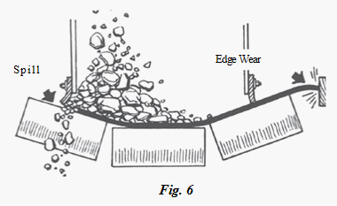
When all portions of a belt run off through a part of the conveyor length, the cause is probably in the alignment or leveling of the conveyor structures, idlers, or pulleys in that region. If one or more portions of the belt run off at all points along the conveyor, the cause is more likely in the belt itself, in the joints of the belt, or in the loading of the belt. When the belt is loaded off-center, the center of gravity of the load tends to find the center of the troughing idlers, thus leading the belt off on its lightly loaded edge (Fig. 6).
These basic rules can be used to diagnose belt running ills. Combinations of these rules sometimes produce cases that do not appear clear-cut as to cause, but if there are a sufficient number of belt revolutions, the running pattern will become clear and the cause disclosed. The usual cases when a running pattern does not emerge are those of erratic running, which may be found with an unloaded belt that does not trough well, or a loaded belt that is not receiving its load uniformly centered.
FACTORS AFFECTING THE TRAINING OF A BELT
Pulleys and Snubs
Relatively little steering effect is obtained from the crown of conveyor pulleys. Crowning is most effective when there is a long unsupported span of belting (approximately four times belt width) approaching the pulley. Since this is not possible on the conveyor carrying side, head pulley crowning is relatively ineffective and is not worth the lateral mal-distribution of tension it produces in the belt.
Tail pulleys may have such an unsupported span of belt approaching them and may be crowned with benefit, except when they are at points of high belt tension. The greatest advantage is that the crown, to some degree, assists in centering the belt as it passes beneath the loading point; this is necessary for good loading.
Take-up pulleys are sometimes crowned to take care of any slight misalignment that occurs in the take-up carriage as it shifts position. In general, crowned pulleys should be used sparingly, if at all, on fabric belts. With steel cord belts, all pulleys must be flat.
All pulleys should be level and should have their axis at 90 degrees to the intended path of the belt. They should be kept that way and not shifted as a means of training, except that snub pulleys can have their axis shifted when other means of training have provided insufficient correction. Pulleys with their axis at other than 90 degrees to the belt path will lead the belt in the direction of the edge of the belt that first contacts the misaligned pulley. When pulleys are not level, the belt tends to run to the low side. This is contrary to the old rule-of-thumb statement that a belt runs to the high side of the pulley. When combinations of these two occur, the one having the stronger influence will become evident in the belt performance.
Carrying Idlers
The belt can be trained with the troughing idlers in two ways. Shifting the idler axis with respect to the path of the belt, commonly known as knocking idlers, is effective where the entire belt runs to one side along some portion of the conveyor. The belt can be centered by knocking ahead (in the direction of belt travel) the end of the idler to which the belt runs (Fig. 7). Shifting idlers in this way should be spread over some length of the conveyor preceding the region of the trouble. It will be recognized that a belt might be made to run straight with half the idlers knocked one way and half the other, but this would be at the expense of increased rolling friction between belt and idlers. For this reason, all idlers initially should be squared with the path of the belt and only the minimum shifting of idlers used as a training means. If the belt is overcorrected by shifting idlers, it should be restored by moving back the same idlers, not by shifting additional idlers in the other direction.
Such idler shifting is effective for only one direction of belt travel. If the belt is reversed, a shifted idler, corrective in one direction, is misdirective in the other. Hence, reversing belts should have all idlers squared up and left that way. Any correction required can be provided with self-aligning idlers designed for reversing operation. Not all self-aligners are of this type, for some work in one direction only.
Return Idlers
Return idlers, being flat, provide no self-aligning influence as in the tilted troughing idlers. However, by shifting their axis with respect to the path of the belt, the return roll can be used to provide a constant corrective effect in one direction. As in the troughing rolls, the end of the roll toward which the belt is shifting should be moved longitudinally in the direction of return belt travel to provide correction.
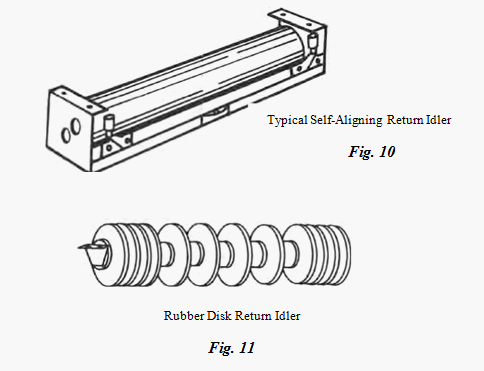
Self-aligning return rolls also should be used. These rolls are pivoted about a central pin. Pivoting of the roll about this pin results from an off-center belt and the idler roll axis thus becomes shifted, with respect to the path of the belt, in a corrective direction (Fig. 10).
Some return idlers are made with two rolls forming a 10-degree to 20-degree V-trough, which is effective in helping to train the return run. The V-return idlers are only recommended for fabric belts wider than 54”. The most important criteria for belt training is idler contact in the center. If the belt has taken a set on the trough side and V-return idlers are being used, the center of the belt is not able to make contact with the center of the V-return idlers. A hold-down roller on the return side will help in training the belt, as it forces the belt to lay flat on the following idlers.
Rubber-segmented disk return idlers (Fig. 11) are used for cleaning the belt and help in belt training. When one of the discs on the edges falls off, the belt edges tend to get caught, forcing the belt to run one way and become a belt de-trainer. Minimum of 8” of belt contact is recommended for disc return idlers.